

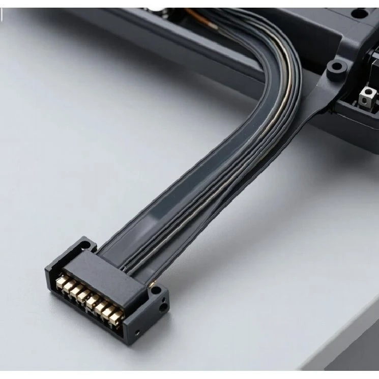
Automotive Instrument Cluster FFC Cable is a flat flexible interconnect for digital instrument clusters and dashboard display assemblies. Pitch, conductor material, cable dimensions, contact plating and termination configuration can be specified to match the required connector interface and assembly dimensions.
Technical Specifications
|
Item |
Specification |
|
Product Type |
Automotive Instrument Cluster FFC Cable |
|
Application |
Dashboard Display / Digital Instrument Cluster |
|
Pitch |
0.3 mm / 0.5 mm / 0.8 mm / 1.0 mm |
|
Pin Number |
Customized |
|
Conductor Material |
Tin-Plated Copper / Copper Alloy |
|
Insulation Material |
PET / PI Film |
|
Cable Length |
Customized |
|
Cable Width |
Customized |
|
Cable Thickness |
Customized |
|
Cable Color |
Customized (Blue / Black / etc.) |
|
Contact Plating |
Gold-Plated / Tin-Plated |
|
Connector Compatibility |
Specified by Mating Connector / Customer Drawing |
|
Production Type |
Prototype & Mass Production |
Contact Configuration
Contact Area
Contact side, exposed contact length and plating can be configured according to the mating connector and customer drawing, with gold-plated or tin-plated contacts available.
Termination Geometry
Contact area, end dimensions and termination structure can be configured to match the specified connector interface.
Stiffener
Stiffener reinforcement can be added at the contact end where required for connector insertion and assembly support.
Connector Compatibility
The contact configuration is matched to the specified mating connector or customer drawing.
FFC Construction
Conductor
Parallel copper conductors form the electrical paths; tin-plated copper or copper alloy can be specified according to the electrical and connector requirements.
Insulation
PET or PI film is selected according to the required cable construction and operating conditions.
Reinforcement / Shielding
Stiffeners or shielding can be added where required by connector insertion, mechanical support or EMI-sensitive routing.
Termination Structure
Contact length, exposed area, contact direction and end geometry are configured to match the mating connector.
Digital Instrument Cluster Applications
Digital Instrument Cluster & Dashboard Displays
TFT/LCD instrument clusters and digital dashboard modules use the FFC for connections between display assemblies and internal electronic boards.
Driver Information & Vehicle HMI
Driver information displays and vehicle HMI interfaces use the cable for compact connections between display electronics and control boards.
Smart Cockpit Display Systems
Integrated smart cockpit assemblies require flat internal connections between display-related modules where dashboard installation space is limited.
EV Instrument & Display Systems
Electric vehicle instrument clusters and digital display assemblies use FFC connections between display modules and their control electronics.
Customization & Prototype Confirmation
Drawing-Based Configuration
Custom FFC production can follow customer drawings covering pitch, pin count, cable dimensions, contact configuration, termination geometry and installation dimensions.
Sample & Assembly Verification
Prototype samples can be checked against the mating connector and instrument cluster assembly for contact position, insertion direction, dimensions and installation clearance.
Approved Specification Control
The approved drawing, sample or part number can be used as the production reference for repeat orders and version control.
Quality Control & Manufacturing
Material Inspection: Copper, insulation film and connector-related materials are checked against specified requirements.
Dimensional Inspection: Pitch, cable width, thickness, length and contact dimensions are checked during production.
Electrical Testing: Continuity, conductor resistance and insulation performance are verified according to the approved specification.
Appearance Inspection: Contact condition, lamination, edge quality and finished cable appearance are checked before packing.
FAQ